The Introduction of Vacuum valve, Vacuum Flanges,Magnetron Sputtering & Vacuum Clamps
The Introduction of Vacuum valve, Vacuum Flanges,Magnetron Sputtering & Vacuum Clamps
Vacuum valve refers to the vacuum system components used in vacuum systems to change the direction of air flow, adjust the amount of air flow, and cut off or connect the pipeline. Vacuum valve closures are sealed with rubber or metal seals.
The bellows of the bellows globe valve are made of stainless steel, high zinc brass JI80, plastic and other materials. Small-diameter (diameters below 10 mm) globe valve closures can be sealed with a diaphragm. Low and medium vacuum can use spherical plug valves.
Vacuum valve model composition:
The correct selection of the valve model and specifications requires understanding of the vacuum valve model; the company’s vacuum valve model programming method is basically similar to ZBJ78016-89 “Vacuum Valve Model, Programming Method”. The product model is composed of a basic model and an auxiliary model, separated by a short horizontal line, and the model composition is as follows:
Represents the range of vacuum used by the product, expressed by the first letter of the Chinese pinyin keyword (printed capitals)
- The representative vacuum range is: low vacuum 105 ~ 10-1Pa (760 ~ 10 Torr)-D;
- The representative vacuum range is: high vacuum 105 ~ 10-4Pa (760 ~ 10-6 Torr)-G;
- The representative vacuum range is: ultra high vacuum 10 ~ 10-7Pa (760 ~ 10-9 Torr)-C;


Represents the valve plate structure or product function category. Its first (or second) letter (print capital) is used as its keyword:
C flapper valve, Q inflation valve, D baffle valve, U ball valve, F flapper valve, W trimmer valve, I butterfly valve, Y differential pressure valve, M diaphragm valve;
Represents the product-driven method, which is represented by the first letter of the Chinese Pinyin keyword (print capitalized):
S manual, D electric, Q pneumatic, C magnetic, Y hydraulic;
Represents the valve channel form, which is represented by the first letter of the Chinese Pinyin keyword (print capital):
Z direct valve, J angle valve, S three-way valve;
Special case: Only valves with inflation are coded with capitalized Chinese letter Q, other types of valves do not use symbols as codes.
Represents product specifications-nominal diameter, expressed in Arabic numerals, the unit is (mm):
For example: DN 16mm, 100mm, 500mm, etc. are expressed by 16,100,500, etc.
Special case: Very few products use Arabic numerals to indicate their performance parameters. For example, “30” in the model of GW-30-T type high vacuum trim valve indicates that the maximum adjustable amount of high vacuum trim valve is 30 Torr.L / S.
The corner note represents the seal structure of the shaft seal. At present, only the stainless steel bellows is used for the shaft seal with the Chinese pinyin lowercase letter b as the code. Other seal structures (such as rubber seals, PTFE, etc.) are not indicated by letters.
Only some products (such as vacuum (pressure) ball valves) use uppercase English letters with parentheses to indicate the connection method or the code of the valve’s main seal and sub-material.
(KF) means adopt GB4982 “Clamping Vacuum Quick-Release Flange” standard, (G) means adopt GB7306 “Cylinder Pipe Thread” standard, (F) means adopt GB6070 “Loop Vacuum Flange” standard, (JB) means JB919-75 “Vacuum Flange” standard H or H (Ⅰ) indicates that the two ends of the valve adopt a welded structure, H (Ⅱ) indicates that the connection end of one end of the valve adopts a welded structure, and the other end uses a plug structure that inserts a rubber tube. ;
Products designed by analogy several times Here are some examples:
- GM-25H (Ⅰ) high vacuum diaphragm valve, nominal diameter 25mm, welding structure at both ends.
- CCQ-150 pneumatic ultra-high vacuum plug-in valve with a nominal diameter of 150mm.
- GID-250 electric high vacuum butterfly valve, nominal diameter 250mm.
4, GUQ-40 (KF) pneumatic high vacuum (pressure) ball valve, nominal diameter 40mm, connection method is GB4982 “Clamping vacuum quick-release flange” DN40 quick-release flange.
- GD-J100b high-vacuum baffle valve, nominal diameter 100mm, the conduction form is angle type, and the shaft seal form is stainless steel metal bellows.
6, DYC-JQ50 electromagnetic vacuum differential pressure valve, nominal diameter 50mm, the conduction form is angle type. (Low vacuum generally only needs the word vacuum).
7, DDC-JQ80 electromagnetic vacuum with inflation valve, nominal diameter 80mm, the conduction form is angle type. (Low vacuum generally only needs the word vacuum).
8, GDC-J25b electromagnetic high vacuum baffle valve, nominal diameter 25mm, the conduction form is angle type. The shaft seal is made of stainless steel metal bellows.
The vacuum valve has the following characteristics:
The pressure is lower than atmospheric pressure, and the pressure drop on the disc must not exceed 1 kgf / cm2. The operating temperature of the medium depends on the process in which the device is used. The temperature generally does not exceed the range of -70 ~ + 150 ° C.
The most basic requirements for this type of valve are to ensure a high degree of tightness of the connection and the tightness of the structure and gasket material.
Vacuum valves can be divided into four groups according to media pressure:
1) Low vacuum valve: medium pressure p = 760 ~ 1 mmHg.
2) Medium vacuum valve: p = 1 × 10⁻³ mm Hg.
3) High vacuum valve: p = 1 × 10⁻⁴ ~ 1 × 10⁻⁷ mm Hg.
4) Ultra-high vacuum valve: p≤1 × 10⁻⁸ mm Hg.
As a closed-circuit valve with a diameter less than 250 mm, the widely used valve bellows has a linear motion vacuum bellows globe valve. Gate valves are subject to greater restrictions, but this is mainly for large bores. Also available are ball stopcocks (ball valves), plunger valves and butterfly valves. Plug valves used as vacuum valves have not been promoted, because the plug valves need to be lubricated with oil, so that oil vapor may enter the vacuum system, which is not allowed. Vacuum valves can be controlled manually and remotely on the spot, as well as electric, electromagnetic drive (solenoid valve), pneumatic and hydraulic controls.
Parameter definition
Nominal diameter: (nominal diameter), also known as the mean outside diameter (mean outside diameter), represents the symbol DN, which is the universal diameter of various pipes and pipeline accessories. Pipes and pipe accessories of the same nominal diameter can be connected to each other and have interchangeability. It is not the outer diameter or inner diameter of the pipe in the actual sense, although its value is closer or equal to the inner diameter of the pipe. , Using the nominal diameter (also known as the nominal diameter, nominal diameter). For example, welded steel pipes can be divided into thin-walled steel pipes, ordinary steel pipes and thickened steel pipes according to their thickness. Its nominal diameter is not the outer diameter or the inner diameter, but a nominal size that approximates the inner diameter of ordinary steel pipes. Each nominal diameter corresponds to an outer diameter, and the value of the inner diameter varies with thickness. The nominal diameter can be expressed in metric mm, or in inch. The pipe accessories are also expressed by the nominal diameter, which has the same meaning as the sewn pipe.
- Nominal pressure: (Nominal pressure), the symbol PN, the maximum allowable working pressure when applied at a certain temperature. For carbon steel body control valve, it refers to the maximum allowable working pressure for applications below 200 ℃; for cast iron body, it refers to the maximum allowable working pressure for applications below 120 ℃; for stainless steel body control valves, it means below 250 ℃ Maximum allowable working pressure during application. When the operating temperature increases, the pressure resistance of the valve body decreases. For example, a carbon steel control valve with a nominal pressure of 6.4 MPa (PN64) has a pressure resistance of 5.2 MPa at 300 ° C, 4.1 MPa at 400 ° C, and 2.9 MPa at 450 ° C. . Therefore, the determination of the nominal pressure of the control valve should not only be based on the maximum working pressure, but also on the maximum working temperature and material characteristics, and not only need to meet the nominal pressure greater than the working pressure.
Function
- Open and close the gas path. When valve 1 and valve 4 are closed and valve 2 is opened, the mechanical vacuum pump III evacuates container I, and the airflow flows through the pre-vacuum extraction line. When valve 2 is closed and valve 4 is opened, the mechanical pump can Evacuate the diffusion pump separately; when valve 1 and valve 4 are opened at the same time, the diffusion pump and mechanical pump can work at the same time to evacuate the container, and the airflow flows through the diffusion pump. It can be seen that the role of the valve in this operation is to open and close the air circuit and change the flow path of the air flow.
- Control the size of the air flow and adjust the vacuum. In Figure 1, you can adjust the opening angle of the bonnet of valve 1 to adjust the amount of air flow through the pipeline. Close valve 2 and valve 4, and the mechanical pump can be supplied through air release valve 3. The inlet of Ⅲ is released into the atmosphere; the vacuum degree in the container can be adjusted through the air release valve 5.
- Quantitative inflation, there is a small hole of a certain volume on the plunger of the glass valve. When the small hole turns to the right and communicates with the high-pressure gas cylinder, the small hole can be filled with high-pressure gas; when it turns to the left and communicates with the vacuum container , Put the volume of high-pressure gas into the container, so it plays the role of quantitative inflation.
There are many types of vacuum valves, which are generally classified according to their functions, structural types, driving methods, materials and applications.
Use
The electromagnetic vacuum belt inflation valve and electromagnetic vacuum differential pressure valve are vacuum valves specially used to prevent mechanical vacuum pumps from returning oil. They are installed at the air inlet of mechanical vacuum pumps and open and close in synchronization with the pumps. Generally can not be used elsewhere, that is to say can not be used for deflation in vacuum systems. The advantage of using the Niwei electromagnetic vacuum differential pressure valve is that it consumes very little power and saves energy; the valve body of DN≤50 is made of aluminum alloy, which is light in weight, small in size and fast in closing the valve plate.
Baffle valves are used in corner and tee positions in vacuum pipes. The driving modes are manual, pneumatic, electromagnetic and electric. The GDC-J electromagnetic high vacuum baffle valve is a metal bellows seal, which has a wide range of applications and can also be used as an inflation valve; the installation position can be arbitrary, can be reversed to an atmospheric pressure, and has a feedback signal output.
The flapper valve is used in places with high vacuum requirements or high pipe sizes. All-way conduction, valve leakage rate is 10-7Pa.L / S, two-way sealed. The driving mode is manual, pneumatic and electric. Both pneumatic and electric with signal feedback device.
Diaphragm and ball valves are straight-through, and can be used in situations where both positive pressure and vacuum coexist. The driving mode is manual, pneumatic and electric.
The butterfly valve is a straight-through type, and the three driving modes of manual, pneumatic and electric are determined by the user. The opening angle of manual butterfly valve can be adjusted arbitrarily; the opening angle of intelligent pneumatic and electric butterfly valve can also be adjusted arbitrarily.
Conditions of use of the valve:
- The medium is pure air or non-corrosive gas.
- The medium temperature is determined by the extreme temperature of the rubber used.
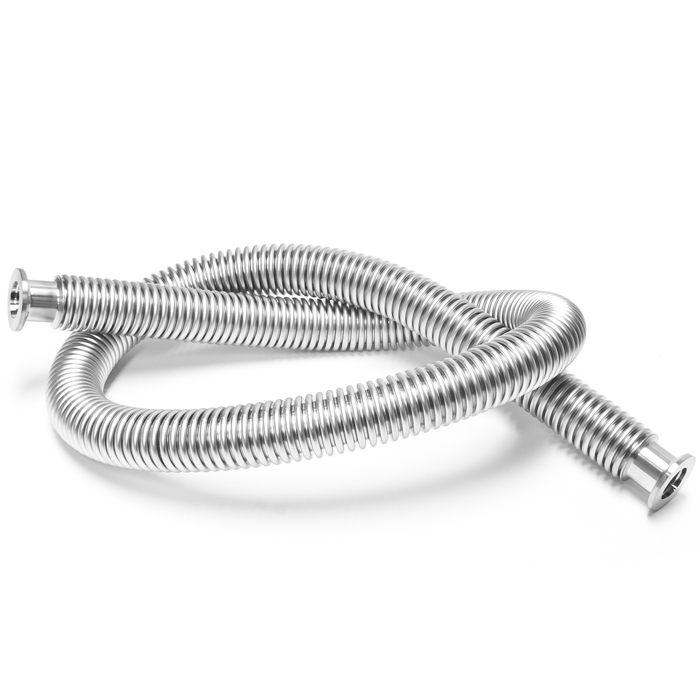
Several common vacuum flange forms in vacuum systems.
Vacuum flange is a kind of removable sealing connection type, which can maintain a certain sealing performance after repeated disassembly and replacement of aging damaged seals. The vacuum flanges commonly used by screw vacuum pump manufacturers mainly include the following 6 types:
1.Rubber sealed vacuum flange
Ordinary rubber sealed vacuum flanges are widely used in high, medium and low vacuum metal systems. If used in ultra-high vacuum systems, another type of rubber sealing flange is required.
2.Fluorine rubber ultra-high vacuum flange
The fluorine rubber ultra-high vacuum flange, as the name suggests, can be used in ultra-high vacuum systems. It uses a fluorine rubber seal ring, and the pipe needs to be welded on both sides, and finished to reduce various defects.
3.Double rubber seal flange
The double rubber sealing flange is mainly used to avoid the outgassing and leakage effects of rubber materials to achieve ultra-high vacuum. Refrigerating the rubber through the intermediate cooling tank or evacuating the middle to achieve the purpose of reducing rubber outgassing and leakage.
4.Vacuum quick release flange
Vacuum quick-release flanges are mainly used for high, medium and low vacuum pipes, and are divided into clamping type and tightening type, usually sealed with O-type rubber seals.
5.Caliper vacuum flange
The caliper vacuum flange is also used for high, medium and low vacuum pipe connections. Forms include caliper screw connection, caliper pad connection and caliper bolt connection.
6.Metal sealing flange
Metal sealing flanges are generally used in ultra-high vacuum systems with a pressure of less than 10-7Pa. The sealing materials are required to withstand high temperature baking above 200 ° C. Commonly used sealing materials are aluminum, copper, and gold.
The screw vacuum pump manufacturer Ke Lexi has a first-class production platform and core patented technology. Its oil-free screw vacuum pump is not only clean and pollution-free, but also has a wide range of pumping speeds and good energy saving, stability, easy maintenance and other advantages. It is widely used in pharmaceutical, chemical, semiconductor and other industries.
Magnetron sputtering is a type of Physical Vapor Deposition (PVD). The general sputtering method can be used to prepare multiple materials such as metals, semiconductors, insulators, and has the advantages of simple equipment, easy control, large coating area, and strong adhesion. The magnetron sputtering method developed in the 1970s achieved high speed, low temperature and low damage. Because high-speed sputtering is performed under low pressure, the ionization rate of the gas must be effectively increased. Magnetron sputtering introduces a magnetic field on the surface of the target cathode and uses the magnetic field to confine charged particles to increase the plasma density and increase the sputtering rate.
Principle
The working principle of magnetron sputtering is that electrons collide with argon atoms during the process of flying to the substrate under the action of the electric field E, and ionize them to produce Ar positive ions and new electrons; new electrons fly to the substrate. Ar ions accelerate to the cathode target under the action of an electric field, and bombard the target surface with high energy, causing the target material to sputter. In the sputtered particles, neutral target atoms or molecules are deposited on the substrate to form a thin film, and the secondary electrons generated will be affected by the electric and magnetic fields, resulting in a direction drift of E (electric field) × B (magnetic field), referred to as E × B drift, whose motion trajectory is approximately
Magnetron sputtering
A cycloid. If it is a toroidal magnetic field, the electrons make a circular motion on the target surface in an approximate cycloidal form. Their motion path is not only very long, but also bound in the plasma region near the target surface, and a large amount of ionization is generated in this region. Ar to bombard the target, thus achieving a high deposition rate. As the number of collisions increases, the energy of the secondary electrons is exhausted, gradually away from the target surface, and finally deposited on the substrate under the action of the electric field E. Because the energy of the electron is very low, the energy transferred to the substrate is small, resulting in a low temperature rise of the substrate.
Magnetron sputtering is a collision process between incident particles and a target. The incident particle undergoes a complex scattering process in the target, collides with the target atom, transfers some momentum to the target atom, and this target atom collides with other target atoms to form a cascade process. During this cascade, target atoms near certain surfaces gain sufficient momentum to move outward and are sputtered out of the target.
Kind
Magnetron sputtering includes many types. Each has different working principles and application objects. However, they have one thing in common: the interaction between the magnetic field and the electric field causes the electrons to spiral in the vicinity of the target surface, thereby increasing the probability of the electrons striking the argon to generate ions. The generated ions impinge on the target surface under the action of an electric field and sputter the target material.
The target source is divided into balanced and unbalanced types. The balanced target source has uniform coating, and the non-balanced target source coating has a strong bonding force with the substrate. Balanced target sources are mostly used in semiconductor optical films, and unbalanced sources are mostly used in wear-resistant decorative films. Magnetron cathodes can be roughly divided into balanced state magnetron cathodes and unbalanced state magnetron cathodes according to the magnetic field configuration. The magnetic flux of the magnetic steel inside and outside the balanced magnetron cathode is approximately equal. The magnetic lines of the two poles are closed on the target surface, which confines the electron / plasma near the target surface, which increases the probability of collision and improves the ionization efficiency. It can glow and maintain glow discharge under working pressure and voltage, and the target utilization rate is relatively high. However, since the electrons are mainly closed to the target surface along the magnetic field lines, the ion bombardment of the substrate area is relatively small. Unbalanced magnetron sputtering technology, that is, the magnetic flux at the outer pole of the magnetron cathode is greater than the inner pole. The magnetic lines of the two poles are not completely closed on the target surface. Some magnetic lines can extend along the edge of the target to the substrate area, so that some electrons can follow the magnetic lines Extend to substrate
Magnetron sputtering
Area plasma density and gas ionization rate. Regardless of balanced or unbalanced, if the magnet is stationary, its magnetic field characteristics determine that the general target utilization rate is less than 30%. To increase target utilization, a rotating magnetic field can be used. But a rotating magnetic field requires a rotating mechanism, while the sputtering rate is reduced. Rotating magnetic fields are mostly used for large or valuable targets, such as semiconductor film sputtering. For small equipment and general industrial equipment, multi-purpose magnetic field stationary target sources are often used.
Sputtering metals and alloys with a magnetron target source is easy, and ignition and sputtering are convenient. This is because the target (cathode), the plasma and the sputtered part / vacuum cavity can form a loop. However, if an insulator (such as ceramic) is sputtered, the circuit is broken. So people use high-frequency power, and add a strong capacitor to the circuit, so that the target becomes a capacitor in the insulation circuit. However, the high-frequency magnetron sputtering power source is expensive, the sputtering rate is small, and the grounding technology is complicated, so it is difficult to adopt it on a large scale. To solve this problem, magnetron reactive sputtering was invented. It is to use a metal target, add argon and a reaction gas such as nitrogen or oxygen. When a metal target collides with a part due to energy conversion, it combines with a reactive gas to form a nitride or oxide.
Magnetron reactive sputtering insulators seem easy, but practical operations are difficult. The main problem is that the reaction occurs not only on the surface of the part, but also on the anode, the surface of the vacuum cavity and the surface of the target source, which causes fire suppression, arcing of the target source and the surface of the workpiece. The twin target technology invented by Leipzig, Germany, solves this problem very well. The principle is that a pair of target sources are cathodes and anodes to each other, thereby eliminating oxidation or nitridation of the anode surface.
Cooling is necessary for all sources (magnetron, multiple arcs, ions), because a large part of the energy is converted into heat. If there is no cooling or insufficient cooling, this heat will make the target source temperature reach more than a thousand degrees and thereby dissolve the entire target source .
Sputtering technology
DC sputtering method
The DC sputtering method requires the target to be able to transfer the positive charge obtained from the ion bombardment process to the cathode in close contact with it, so this method can only sputter conductive materials and is not suitable for insulating materials. Because the ionic charges on the surface cannot be neutralized when bombarding an insulating target, this will cause the target surface potential to increase, and almost all the applied voltage will be applied to the target. The chance of acceleration and ionization of the ions between the two poles will become smaller, or even not ionize As a result, continuous discharge cannot be achieved or even discharge stops, and sputtering stops. Therefore, for insulating targets or non-metal targets with poor conductivity, radio frequency sputtering (RF) must be used.
The sputtering process involves a complex scattering process and a variety of energy transfer processes: the incident particles collide with the target atoms elastically, and a part of the kinetic energy of the incident particles will be transferred to the target atoms; the kinetic energy of some target atoms exceeds that of their surroundings. The potential barrier formed by other atoms (5-10 eV for metals), which is then collided from the lattice lattice to produce off-site atoms; these off-site atoms further repeatedly collide with nearby atoms in sequence to produce collisions Cascade; when this collision cascade reaches the target surface, if the kinetic energy of the atoms near the target surface is greater than the surface binding energy (1-6eV for metals), these atoms will detach from the target surface and enter a vacuum.
Sputter coating
Sputter coating is a technology that uses charged particles to bombard the target surface in a vacuum, so that the bombarded particles are deposited on the substrate. Generally, a low-pressure inert gas glow discharge is used to generate incident ions. The cathode target is made of coating material, the substrate is used as the anode, and 0.1-10Pa argon or other inert gas is passed into the vacuum chamber. The cathode (target) is 1-3KV DC negative high voltage or 13.56MHz RF voltage. Light discharge. The ionized argon ions bombard the target surface, causing the target atoms to splash out and deposit on the substrate to form a thin film. There are many sputtering methods, including two-level sputtering, three-level or four-level sputtering, magnetron sputtering, target sputtering, radio frequency sputtering, bias sputtering, asymmetric AC radio frequency sputtering, and ion beam sputtering. And reactive sputtering.
Because the sputtered atoms are spattered after exchanging kinetic energy with positive ions with tens of electron volt energy, the sputtered atoms have high energy, which is conducive to improving the diffusion ability of the atoms during deposition, and increasing the compactness of the deposited tissue, The produced film has strong adhesion to the substrate.
During sputtering, after the gas is ionized, the gas ions fly to the target connected to the cathode under the action of the electric field, and the electrons fly to the grounded wall cavity and the substrate. In this way, under low voltage and low pressure, the number of ions generated is small, and the sputtering efficiency of the target is low; while under high voltage and high pressure, although more ions can be generated, the electrons flying to the substrate carry high energy. , It is easy to cause the substrate to generate heat or even cause secondary sputtering, which affects the quality of the film. In addition, the probability of collision of target atoms with gas molecules during the process of flying to the substrate is also greatly increased, so it is scattered to the entire cavity, which will not only cause waste of the target, but also cause each layer when preparing a multilayer film. Pollution.
DC magnetron sputtering
In order to solve the defects of cathode sputtering, people developed a DC magnetron sputtering technology in the 1970s, which effectively overcomes the disadvantages of the low cathode sputtering rate and the increase of the temperature of the substrate by the electrons, and thus has achieved rapid development. And widely used.
The principle is that in the magnetron sputtering, since the moving electrons are subjected to Lorentz force in the magnetic field, their motion trajectory will bend or even generate spiral motion, and the motion path becomes longer, which increases the collision with the working gas molecules Times, the plasma density is increased, so that the magnetron sputtering rate is greatly improved, and it can work at a lower sputtering voltage and air pressure to reduce the tendency of film contamination; The energy of the atoms on the bottom surface can therefore greatly improve the quality of the film. At the same time, when the electrons that have lost energy after many collisions reach the anode, they have become low-energy electrons, so that the substrate will not be overheated. Therefore, the magnetron sputtering method has the advantages of “high speed” and “low temperature”. The disadvantage of this method is that an insulator film cannot be prepared, and the uneven magnetic field used in the magnetron electrode will cause significant uneven etching of the target, resulting in a low target utilization rate, generally only 20% -30%.
Main uses of magnetron sputtering equipment
(1) Various functional films: such as films with absorption, transmission, reflection, refraction, and polarization functions. For example, a silicon nitride antireflection film is deposited at low temperature to improve the photoelectric conversion efficiency of a solar cell.
(2) Applications in the field of decoration, such as various total reflection films and translucent films, such as mobile phone cases, mice, etc.
(3) As a non-thermal coating technology in the field of microelectronics, it is mainly used in chemical vapor deposition (CVD) or metal organic
(4) Chemical vapor deposition (CVD) is difficult to grow and is not suitable for thin film deposition of materials, and a large area of very uniform thin films can be obtained.
(5) In the optical field: IF closed-field non-equilibrium magnetron sputtering technology has also been applied in optical thin films (such as antireflection coatings), low-emissivity glass, and transparent conductive glass. In particular, transparent conductive glass is currently widely used in flat panel display devices, solar cells, microwave and radio frequency shielding devices and devices, and sensors.
(6) In the mechanical processing industry, the surface deposition technology of surface functional films, super hard films, and self-lubricating films has been greatly developed since its introduction, which can effectively improve surface hardness, composite toughness, wear resistance, and high temperature chemical stability. Performance, thereby greatly improving the service life of coated products.
In addition to the above-mentioned fields that have been widely used, magnetron sputtering also plays an important role in the research of high-temperature superconducting films, ferroelectric films, giant magnetoresistive films, thin-film light-emitting materials, solar cells, and memory alloy films.
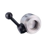
In vacuum clamping, the workpiece is firmly pressed on the table by the external atmospheric pressure. Rather than what is commonly thought of as “sucking” on the bench. The lateral force that the workpiece can withstand is mainly determined by the surface structure, the air pressure difference, and the contact area. The larger the contact area, the greater the clamping force.
The concept of vacuum
Vacuum refers to the absence of any substance in a certain space. But in fact we usually call the air pressure in a certain space less than atmospheric pressure as vacuum.
Units of measurement
The most commonly used units are Pascal and bar
100 Pa = 1 hPa
1 hPa = 1 mbar
1 mbar = 0,001 bar
Vacuum clamping technology
Vacuum clamp systems are commonly used to quickly clamp wood, plastic, and non-ferrous metals. They are compatible with CNC machines. Here, vacuum fixtures are mainly used in special machining systems; for example, clamping one side of an aluminum plate and machining the other five sides. This can increase production and reduce costs: vacuum fixtures do not damage the clamping surface, and do not require time-consuming and laborious work to align the workpiece. The latest vacuum fixture system can realize the rapid replacement of workpieces of different specifications and shapes.
Generate clamping force
The surface of any object is subject to an atmospheric pressure of 1 bar. The vacuum chuck exhausts the air in the sealed area below the workpiece, so that the contact surface of the workpiece is not subject to a small atmospheric pressure. This creates a pressure difference. It depends on the performance of the vacuum chuck, which is generally 0.7-0.8 bar. This means that if a vacuum of 200 mbar is traveled, a pressure of 800 mbar (approximately 0.8 kp / cm) will be generated on the workpiece. The amount of clamping force is only related to the clamping area.
Calculation formula
Clamping force = pressure X area
F (N) = bar x A (m²) x 105
Bar1 bar = 10 N / cm²
Vacuum fixture application
Vacuum clamps can be used to clamp non-magnetic materials, such as non-ferrous metals such as aluminum, copper, alloys, and polymer materials such as wood.