α-2400U Inert Vacuum Controlled Atmospheres Laboratory Glovebox

α-2400U Inert Vacuum Controlled Atmospheres Laboratory Glovebox |
|||
|---|---|---|---|
| External Structure |    |
||
| Chamber Capacity | Approximately 57 cu.F.t (1.6 m³) | ||
| Overall Dimensions | 126″ L x 31.5″ W x 74.8″ H
3200mm (L) x 800mm (W) x 1900mm (H) |
||
| Overall Weight | 640 kg (1400 lbs) | ||
| Electrical Voltage | • 230 VAC/50-60 Hz, 10 A
• 115 VAC/50-60 Hz, 20 A • 100 VAC/50-60 Hz, 20 A |
||
Glovebox Chamber |
|||
| Description | Material | Stainless Steel Type 304 (USA), 3.0 mm in thicknes | |
| Internal Dimensions | 94.5″ L x 29.5″ W x 35.4″ H
2400mm (L) x 750mm (W) x 900mm (H) |
||
| Inclined Front Window | Material | Tempered glass, 8.0 mm in thickness,Lexan (polycarbonate) 10 mm in thickness upon request | |
| Dimensions | 44″Lx33″ W
1120mm (L) x 840mm (W) |
||
Glove Ports |
Tecaform | 220 mm (8.6″)in diameter, O-ring sealed |  
|
| Material | Hard aluminum alloy or polyaldehyde upon request | ||
Gloves |
Material | Butyl rubber | |
| Thickness | 0.4 mm,(standard)
0.8 mmupon request |
||
HEPA Filters |
• Inlet and outlet filters eliminate particles with the size > 0.3μm | ||
| Lighting | • Fluorescent lamp, front mounted | ||
| Leak Rate | Typically
· by oxygen leak decay test method according to ISO 10648-2: 1994, · by Pressure Change Test Method according to ISO 25412 |
||
Gas Purification System |
|||
| Description | • Automated removal of H2O and O2
• Single column, automated column regeneration; dual purification columns (optional) • Enclosed stainless steel loop for gas recirculation and purification |
||
| Operating Gas | Working gas | Nitrogen, Argon, or Helium (purity >99.999%) | |
| Column regeneration gas | Mixture of H2 (5-10%) and working gas | ||
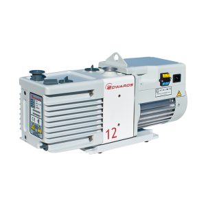
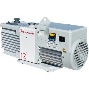
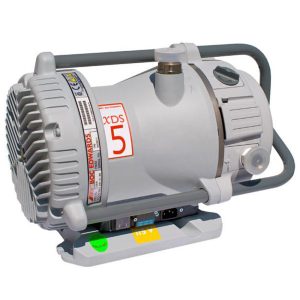
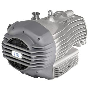
Vacuum Pump |
Description | Rotary vane pump, installed with oil mist filter, oil circulator, and automatic gas ballast control; dual-stage.
Or dry pump upon request |
  |
| Pumping rate | 7.0 CFM (12 m³/h) | ||
| Ultimate vacuum | -3 mbar | ||
Circulation Unit |
Material | Integrated blower, oil-free, highly efficient | |
| Flow Rate | 47 CFM (80 m³/h) | ||
| Leakage Rate | • Leak rate -5 mbar l/s | ||
| Valves | • Electro-pneumatic DN 40 |
||
| Leakage Rate | Typically
· by oxygen leak decay test method according to ISO 10648-2: 1994, · or by Pressure Change Test Method according to ISO 25412 |
||
| LCD or LED Display | LCD, Pressure, O2 and H2O value is logged for 24 hours | ||
Antechamber |
|||
Main Antechamber |
Material | Stainless Steel Type 304; 3.0 mm in thickness | |
| Internal Dimensions | 14″(Φ) x 23.6″(L)
360mm (Φ) x 600mm (L) |
||
| Vacuum | 1 x 10⁻² mbar | ||
Mini Antechamber |
Material | Stainless Steel Type 304 (USA); thickness 3.0 mm | |
| Inside dimensions | 5.9″(Φ) x 13″(L)
150mm (Φ) x 330mm (L) |
||
| Vacuum | 1 x 10⁻² mbar | ||
Purging System |
|||
| Function | By setting up the purging time and pressure, the system automatically purges the chamber O2 level, timer or manually controlled |
||
Analyzer |
|||
O2-Analyzer |
Dimensions | 8″ L x 3″ D x 2.4″ H
205mm (L) x 80mm (W) x 60mm (H) |
  |
| Measurement Range | 0 to 1000 ppm (V) | ||
| Other Analyzer | GE oxy.IQ™ Oxygen Transmitter upon request | ||
H2O-Analyzer |
Dimensions | 8″ L x 3″ D x 2.4″ H
205mm (L) x 80mm (W) x 60mm (H) |
  |
| Measurement Range | 0 to 1000 ppm (V) | ||
| Other Analyzer | GE VeriDri™ Dew-Point Transmitter | ||
Solvent Purification System |
|||
| Description | Column Material | Stainless Steel Type 304 (USA); 3.0 mm in thickness | |
| Inside Dimensions | 8.6″(Φ) x 17.7″(L)
220mm (Φ) x 450mm (H) |
||
| Packing Material | High-quality activated carbon | ||
Optional Components |
|||
| Vacuum feedthrough with two valves | Stainless Steel Type 304 | ||
| Electrochemical signal feedthrough | 4 or 8 pins, Stainless Steel Type 304 | ||
Freezer |
Location | Integrated on the side panel of the glovebox | |
| Inside dimensions | 16.6″ L x 10.5″ W x 6.4″ D
423mm (H) x 266mm (W) x 162.5mm (D) |
||
| Capacity | 18 L or 32 L, 5 shelves with adjustable height | ||
| Minimum Temperature | -35 ℃ | ||
Microscopes with CCD Camera Systems |
• 10x, 20x, and 40x targets, 5.0 M CCD | ||
| Cold well with cover | Capacity | Diameter: 6.3″ (160 mm) Depth: 7.9″ (200 mm) |
|
| Minimum Temperature | -120 ℃ | ||
| Dual Purification Columns | More efficient to remove oxygen and moisture | ||
| Organic Solvent Absorber | Regenerable, more efficient to purify organic solvent | ||
| Cooling Fan | Accelerate the gas flow in the glovebox chamber | ||
| Heating Element | Installed in Main Antechamber; Maximum 200 ℃; Temperature control ±1 ℃. | ||
Other Intormation |
|||
| Compliance | UL certified, ISO9001 certified, and CE certified | ||
| Warranty | Glovebox | One year limited warranty, and lifetime technical support | |
| Exceptions | • Rusting or damage due to improper storage or maintenance
• Consumable items such as gloves and oxygen sensors |
||
| Application Notes & Warnings |
• The interconnections between the glove-box chamber and the gas purification system must be unimpeded during the purification cycles
• The use of corrosive gases is prohibited because they will damage the water and oxygen sensors • Regularly perform regeneration to maintain the optimum purification efficiency • The O2 removing rate is largely dependent on the type of purging gas used. For faster chamber purging process, Nitrogen is preferred over Argon due to its lighter mass • Corrosive liquid (such as LiPF6 electrolyte) must be sealed in a container inside the glove box. Otherwise, liquid vapour may condense and corrode the steel chamber and purification pipeline |
||