Motion Control Requirements for Hermetic Seam Welding
Advances in electronics and battery technology have led to an increase in the number and sophistication of electronic devices that are implanted in the human body for treating an ever-growing number of afflictions. This technology has been used successfully for many years in pacemakers, defibrillators and other cardio- rhythm management devices.
Advances in electronics and battery technology have led to an increase in the number and sophistication of electronic devices that are implanted in the human body for treating an ever-growing number of afflictions. This technology has been used successfully for many years in pacemakers, defibrillators and other cardio-rhythm management devices. The last few years have seen significant growth in implantable pulse devices (e.g., neurostimulators) for the treatment of chronic pain. All of these components share a common packaging technology that consists of two titanium half-shells that are joined together with a hermetic seam weld. A hermetic seal is defined as an airtight interface, a critical requirement to protect the patient from a potential source of infection throughout the lifetime of the device. The application of the seal around the periphery of the package is a critical task that has been limited by the capability of the motion control platform.
The sealing of these packages is done with a YAG-based laser welding system with the titanium half-shells affixed to a three-axis X/Y/rotary system. An additional linear axis may be required if the seam is not in one plane, which is typically the case if the weld must wrap around features on the device to accommodate attachment points of leads that are used to transmit electrical stimuli to treatment areas in the body. The X/Y/theta system can be a single stack, or a split design with different combinations of the linear and rotary axes in two separate assemblies.
The welding process consists of coordinated motion between the X, Y and rotary axes to maintain the weld point on the part in the focal position of the laser. Only a single- axis move is required for straight sections of the weld. When radii are encountered in the profile, the part must rotate in proportion to the change in angle along the surface with both linear axes moving to maintain weld focal position. The speed along the weld seam must also be held constant, ensuring consistent spot overlap and maintaining the integrity of the hermetic seal. The required movement of the axes along with the specification of axis velocity is not intuitive and must be created off-line using a CAD/CAM package that has been configured to support this specific mechanical configuration. The CAM package breaks up the weld profile into small, discrete steps along the weld seam path and calculates the required X, Y and rotary positions to maintain focus and constant surface speed. The small segment sizes required to maintain good weld quality can result in a very large motion program with hundreds of lines of code.
One significant drawback to the CAM-generated approach is the loss of a direct correlation between a line in the program and a feature on the part. This makes it impossible to manipulate the program by hand to optimize weld quality by adjusting the motion profile or the weld velocity over a specific region of the part. All changes must be made in the CAD/CAM software and a new program created to run on the controller. The CAD/CAM software is not often installed on the machine controller, which results in additional delays in processing as files are transferred back and forth on company intranets or the reliable (but slow) “sneaker-net”.
There is an alternative method (of implementing the hermetic seam-welding process) that retains the connection between part geometry and the programmed tool path. For many years robotic controllers have used on-line kinematics that transform X/Y/Z positions into angular joint positions. The application of these transforms can be defined by a closed-form function – position and velocity commands in the part coordinate space are run through a series of matrix-based multiplications with boundary checks to avoid invalid and redundant robot positions, and to create position and velocity commands for the robot. The user programs in the part coordinate space, and the controller converts this information into robot coordinate space in real time.
An approach similar to the robotic control technique can be applied to the hermetic seam-welding application. The controller implementing the transformation in this case must have knowledge of the type of motion being commanded, as there are distinctly different transformation functions for linear and circular movements. Modern open-architecture motion controllers, such as Aerotech’s Automation 3200 software-based system, support this functionality. The mathematical relationship that defines the movement of the part in X/Y/Z space to motion on the X/ Y/rotary subsystem is run in a task on the controller. The user program is written in the coordinate system of the part and contains only as many program lines as there are arc and line segments in the actual part geometry. This results in a one-for-one correspondence between lines in the motion program and features on the part.
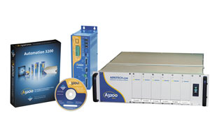
Aerotech’s Automation 3200 software-based motion controller.
If the geometry or weld velocity must be adjusted to optimize the weld process, it can be done on the machine without having to re-post the program.
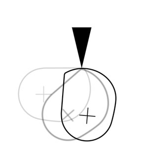
Center of rotation translation for fixed focus.
The point in space about which the part rotates is a parameter that can be changed on a part-by-part basis, if desired. The identification of the rotation point relative to the part can be automated with a vision system before welding. This reduces the accuracy requirements of the fixture, resulting in reduced tooling costs.
A critical advantage of programming in the part coordinate frame is that the commanded positions of the Cartesian space can be used to trigger the laser at precise locations along the periphery of the part to ensure the integrity of the hermetic weld. Weld speeds are sufficiently slow compared to the motion control interpolation rate. Therefore the repetition rate of the laser can be synthesized in real time by calculating the vector displacement around the part during the welding process. If the programmed welding speed is modified to improve positioning tolerance over critical features on the package, the repetition rate of the laser will be automatically adjusted to maintain the desired weld spot overlap. In traditional welding processes, the weld speed is held constant and is set to the lowest speed that will ensure good weld quality around the part. Having the flexibility to weld faster over straight segments and to slow down for small arcs, while maintaining spot overlap, can result in a significant reduction in overall weld time.
Advances in control technology show great promise in reducing the programming complexity and weld cycle times while improving the quality of the hermetic seal. As the number of implantable devices proliferates and more suppliers begin to enter the marketplace, this technology will become an important factor in ensuring high quality, cost-effective manufacturing processes.