The Introduction of Bellows Hose
The Introduction of Bellows
The corrugated tube refers to a tubular elastic sensitive element connected by a foldable wrinkle sheet in a folding and stretching direction. Bellows are widely used in instrumentation. The main purpose is to be used as a measuring element of pressure measuring instruments to convert pressure into displacement or force. The bellows has a thin wall and high sensitivity, and the measurement range is from tens of Pascals to tens of Megapascals. Its open end is fixed, the sealed end is in a free state, and the auxiliary coil spring or reed is used to increase elasticity. During work, it is extended along the length of the tube under the effect of internal pressure, so that the movable end has a displacement that has a certain relationship with the pressure. Moving the pointer on the movable end can directly indicate the amount of pressure. The bellows is often combined with a displacement sensor to form a pressure sensor that outputs electrical energy, and is sometimes used as an isolation element. Since the expansion of the bellows requires a large volume change, its response speed is lower than that of the Bourdon tube. Bellows are suitable for measuring low pressure.
Type of bellows
The bellows mainly include metal bellows, vacuum bellows, bellows expansion joints, bellows heat transfer tubes, diaphragm boxes and metal hoses. Metal bellows are mainly used to compensate pipeline thermal deformation, shock absorption, and absorption of pipeline settlement deformation, and are widely used in petrochemical, instrumentation, aerospace, chemical, power, cement, metallurgy and other industries. Corrugated pipes of other materials, such as plastic, have an irreplaceable role in the fields of media transmission, power threading, machine tools, and home appliances.
Bellows: A kind of pressure measuring elastic element in a pressure measuring instrument. It is a cylindrical thin-walled corrugated shell with multiple lateral corrugations. The bellows is elastic and can produce displacement under the action of pressure, axial force, lateral force or bending moment. Bellows are widely used in instrumentation. The main purpose is to be used as a measuring element of pressure measuring instruments to convert pressure into displacement or force. The bellows has a thin wall and high sensitivity, and the measurement range is from tens of Pascals to tens of Megapascals. In addition, the bellows can also be used as a sealing and isolating element to separate the two media or prevent harmful fluids from entering the measuring part of the device. It can also be used as a compensating element to compensate for the temperature error of the instrument using its volume variability. It is also sometimes used as an elastic coupling joint of two parts. The bellows can be divided into metal bellows and non-metal bellows according to the constituent materials; according to the structure, it can be divided into single-layer and multi-layer. Single-layer bellows are more commonly used. Multi-layer bellows have high strength, good durability and low stress, and are used in important measurements. The materials of bellows are generally bronze, brass, stainless steel, Monel and Inconel.
Performance
Stiffness
The value of the load required to make a metal bellows or other elastic element to produce a unit displacement is called the stiffness of the element, and is generally expressed by “K”. If the elastic properties of the element are non-linear, the stiffness is no longer constant, but changes with increasing load. The elastic tolerance of bellows for general engineering can be limited within +/- 50%. The stiffness of the corrugated pipe is divided into axial stiffness, bending stiffness, torsional stiffness, etc. according to different load and displacement properties. In the application of bellows, most of the stress conditions are axial loads, and the displacement mode is linear displacement. The following are the main calculation methods for designing the axial stiffness of bellows:
- Energy method for calculating stiffness of bellows
- Empirical formula to calculate the stiffness of bellows
3. Numerical method for calculating the stiffness of bellows
4. EJMA standard stiffness calculation method
- Japan TOYO method for calculating stiffness
- US KELLOGG (new method) method for calculating stiffness
In addition to the above six methods of calculating stiffness, there are many other methods of calculating stiffness abroad that are not described here. Chinese mechanics have done a lot of work in the theoretical research and experimental analysis of bellows, and have achieved fruitful research results. The main research methods are:
(1) Perturbation method
(2) Initial parameter method for numerical integration
(3) Integral equation method
(4) Perturbed finite element method
All of the above methods can perform relatively accurate calculations on bellows. However, due to the application of deeper theories and methods of computational mathematics, it is difficult and difficult to master in engineering applications, and further popularization is needed.
Stiffness calculation of metal bellows and coil spring
In the process of use, when the rigidity is required to a large extent, and the rigidity of the metal bellows itself is relatively small, it may be considered to arrange a cylindrical coil spring in the inner cavity or the outside of the bellows. This can not only improve the stiffness of the entire elastic system, but also greatly reduce the error caused by hysteresis. The elastic performance of this elastic system mainly depends on the characteristics of the spring and the stability of the effective area of the bellows.
Bending stiffness of bellows
Stress calculation of bellows
As an elastic sealing part, a metal bellows must first meet the strength conditions, that is, its maximum stress does not exceed the allowable stress under given conditions. The allowable stress is obtained by dividing the ultimate stress by the safety factor. According to the working conditions of the bellows and the requirements for its use, the ultimate stress can be the yield strength, the critical stress when the bellows is unstable, or the fatigue strength. To calculate the maximum working stress of the bellows, the stress distribution in the wall of the bellows must be analyzed.
The stress on the bellows is caused by the pressure in the system and the deformation of the bellows. Pressure creates ring (circumferential) stress on the bellows, while radial films and bending stresses occur on the side walls, troughs, and crests of the wave. A thin shell that cannot be bent is sometimes called a thin film, and the stress calculated by ignoring bending is called a thin film stress. When the bellows deforms, it generates radial film stress and bending stress. When the bellows work, some bear the internal pressure and some bear the external pressure, such as bellows expansion joints and metal hoses. In most cases, the bellows bears the inner pressure. The bellows used for valve stem sealing are generally Withstand external pressure Here we mainly analyze the stress of the bellows when it is under internal pressure. The ability of the bellows to withstand external pressure is generally higher than its ability to withstand internal pressure. With the wide application of bellows, people have carried out a lot of analysis and experimental verification of the stress of the bellows, and put forward many calculation formulas, calculation programs and charts for engineering design. However, some methods are inconvenient to use due to complicated diagrams or programs, and some methods assume conditions that are either too simplified or too ideal, making it difficult to ensure safety and reliability in use, and many methods have not been accepted by the engineering community. Therefore, there are few methods that truly meet practical requirements. There are two commonly used methods:
- Numerical method for calculating stress of bellows
It is assumed that all the corrugations of the bellows are in the same condition, and only a single half wave of the bellows ripples is studied in the calculation. In this way, the end ripple is not considered in the study, although the boundary conditions of the end ripple are different from the middle ripple. The numerical method is based on E. Lesnell solved the nonlinear equations listed in the case of the axially symmetric deformation of the rotating shell with variable wall thickness. E. in derivation In the Lesnell equation, the general assumptions of the thin shell theory are applied, including: the assumption that the thickness is small compared with the principal radius of curvature of the torus; the assumption that the material is homogeneous and isotropic. Adopting the above assumptions will also bring some errors to the calculation. Because in the manufacture of corrugated pipes, the rolling, drawing and subsequent corrugated plastic forming of the tube blank will cause anisotropy and non-uniformity in the mechanical properties of the material.
- American EJMA Stress Calculation Method
Calculation of effective area of bellows
The effective area is one of the basic performance parameters of the bellows. It represents the ability of the bellows to convert pressure into concentrated force. In the case of using the bellows to convert pressure into concentrated force output, the effective area is an important parameter.
When a bellow is used in a force-balanced instrument, the stability of its effective area will directly affect the accuracy of the instrument. Therefore, in this case, not only the reasonable effective area of the bellows is required, but also the effective area does not change with the working conditions during the working process.
- The concept of effective area and changes in effective area
The effective area is an equivalent area, and pressure exerts equal axial force on this area. In general, as the internal pressure increases, the effective area of the bellows becomes smaller, and as the external pressure increases, the effective area becomes larger.
- Volume effective area of bellows
Under the action of external force or pressure difference, the ratio of the volume change of the bellows to the corresponding effective length is called the volume effective area.
3. Calculation of effective area of bellows
The requirements for the effective area of the bellows and their calculation methods depend on the purpose of the bellows. If the bellows is used as an elastic seal or thermal compensation of the pipeline, the meaning of the effective area is only used to calculate the axial force when the bellows is formed and the thrust in the system. There are some differences between the calculated value of the effective area of the bellows and the measured value. In general, using a special formula to calculate the effective area of the bellows can meet the needs.
When the bellows is used for force balancing instruments and field platforms that need to convert pressure to force, its effective area should be accurately determined and measurements should be taken one by one.
Sensitivity
The extravagant amount of metal bellows and other elastic components under unit load is called the sensitivity of the component. Stiffness and sensitivity are the main functional parameters of bellows and other elastic components, but they are two different ways of expressing the same usage characteristics. For different occasions, to facilitate the analysis of the problem, any of these parameters can be used.
Effective area
For an elastic element that achieves pressure-to-force or force-to-pressure conversion, another important functional indicator is the effective area. The effective area refers to the amount of elastic force that can be converted into a concentrated force under the unit pressure when its displacement is zero.
Service life
There are two states when the elastic element works; one is working under a certain load and displacement, and the load and displacement are kept constant or rarely changed, which is called static work; the other use case is load and displacement The cycle changes back and forth. The component is in cyclic operation. Due to different working conditions, the modes of component damage or failure are also different. The instrument’s elastic sensitive components work in the elastic range, basically in a static working state, and have a long service life, generally reaching tens of thousands to hundreds of thousands of times. The bellows components used in engineering sometimes work in the elastoplastic range or alternating stress state, and the life is only hundreds of dry times. The components must be given a permissible working life when they are cycled, and the number of cycles, time, and frequency must be specified.
The rated life of an elastic component is the expected life set during the design of the component. It is required that the component should not be fatigued, damaged or failed during this period.
Tightness
Hermeticity refers to the performance of the component to ensure no leakage under a certain internal and external pressure difference. When the bellows-type components work, the inner cavity is filled with a gas or liquid medium and has a certain pressure, so the tightness must be guaranteed. Testing methods for air tightness include air tightness test, leak test, liquid pressure test, soap water or helium mass spectrometer leak detector.
Natural frequency
The elastic components used in industry often have a certain degree of vibration in the working environment, and some components are used as vibration isolation components. It is under vibration. For elastic components applied under special conditions, the natural frequency of the component (especially the fundamental frequency) must be prevented from being close to the vibration frequency of any vibration source in the system to avoid damage caused by resonance. Corrugated tube components have been widely used in various fields. In order to avoid damage to the resonance surface of the corrugated tube, the natural frequency of the corrugated tube should be lower than the vibration frequency of the system, or at least 50% higher than the vibration frequency of the system.
Operating temperature
Metal bellows components have a wide temperature range, and are generally given before the design and manufacture of elastic components. For some special-purpose bellows, the inner cavity passes liquid oxygen (-196 ° C) or lower temperature liquid nitrogen, and the pressure resistance is up to 25MPa. Large-scale corrugated expansion joints for connection of pipe network systems (the nominal diameter sometimes exceeds lm) require a pressure of 4MPa, a temperature resistance of 400 ° C, and a certain degree of corrosion resistance. The temperature adaptability of the elastic element depends on the temperature resistance of the elastic material used. Therefore, according to the operating temperature range of the elastic element, an elastic material with suitable temperature performance parameters can be used to process and produce qualified bellows components.
Technical parameter editing
Carrying load
Various expected load values acting on metal bellows and other elastic elements, such as concentrated force F, pressure p and moment M, etc. When the metal bellows-type elastic element is used, in addition to the given load value, the direction and location of the load must be given. For compressive loads, it should also be stated that the elastic element is subjected to internal or external cavity pressure.
The maximum load value or full-scale value allowed for metal bellows and other elastic components under normal operating conditions. It is usually the expected design value, or the modified design value after actual testing of the product prototype.
The bearing capacity of a specific elastic component product when it is subjected to transients or during testing is allowed to exceed the rated load without damage, failure, and instability. For instrument elastic sensitive components, the overload capacity is generally limited to 125% of the rated load. Bellows components used in engineering are generally limited to 150% of the rated load. According to engineering requirements, when a large safety factor is required, the provisions of the used elastic elements do not allow any overload, so the load must be less than or equal to the rated load value.
Displacement characteristics
The position of a specific point (free end or center) in a metal bellows and an elastic element changes. According to its movement trajectory, it can be divided into linear displacement and angular displacement. Under external load, the metal bellows may produce axial displacement, angular displacement and lateral displacement.
The displacement value caused by metal bellows and elastic components under the rated load, that is, the working displacement that they are allowed to generate under normal use conditions.
All kinds of elastic elements can withstand the rated displacement capacity at the moment of operation or during the test. When an overload displacement occurs, the elastic element should not be damaged, failed, or unstable. For instrument elastic sensitive components, the overload displacement is generally limited to 125% of the rated displacement. The bellows components used in the project should be determined according to the engineering conditions and the degree of safety.
Elastic properties
The relationship between the displacement and load of a metal bellows and other elastic components on a given cook is called elastic characteristics, and the displacement and load should be stored in the elastic range of the component material. The elastic characteristics of the bellows components can be used as a function Equations, tables and graphs. Its elastic characteristics depend on the structure and loading method of various elastic elements. The elastic characteristics of components can be linear or non-linear. Non-linearity can also be divided into two types: increasing characteristics and decreasing characteristics.
Elasticity is a main performance index of bellows and other elastic components. The elastic components used in instruments and measuring devices are generally designed to make the output of the component and the measured parameter (load) have a linear relationship. In this way, a simpler transmission amplification mechanism can be used to achieve the equal division of the meter.
Residual deformation
The residual deformation of metal bellows and other elastic components refers to the displacement of the components after loading, but the elastic components cannot return to their original positions after a considerable period of time after unloading. Produces a residual value for permanent deformation. The residual deformation of the component is related to the use state. When the tensile (or compression) displacement gradually increases to a certain displacement value, the residual deformation will increase significantly.
Residual deformation is a parameter that determines the deformability of elastic components. For elastic sensitive components, if a large residual displacement occurs after reaching the rated displacement value, this will affect the measurement accuracy of the meter. therefore. Generally, a certain limit value is given to the amount of residual deformation. Corrugated tube components (such as bellows expansion joints) used in engineering, sometimes in order to obtain larger displacements, make the components work in the elastoplastic area, which will cause large residual deformation. If it can meet a certain service life without failure. At this time, the amount of residual deformation is no longer considered.
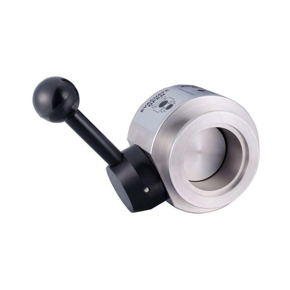
Design
The theoretical basis of metal bellows design is plate and shell theory, material mechanics, and computational mathematics. There are many parameters for the design of the bellows. Due to the different uses of the bellows in the system, the emphasis of its design calculations is different. For example, bellows are used for force balancing components, which require the effective area of the bellows to be constant or change little within the working range. For measuring components, the elastic characteristics of the bellows are required to be linear; for vacuum switch tubes as vacuum seals The vacuum tightness, axial displacement and fatigue life of the bellows are required; for the valve as a seal, the bellows should have a certain pressure resistance, corrosion resistance, temperature resistance, working displacement and fatigue life. According to the structural characteristics of the corrugated pipe, the corrugated pipe can be regarded as a ring shell, a flat cone shell or a ring plate. The design and calculation of the bellows is the design and calculation of a circular shell, a flat cone shell or a ring plate.
The calculated parameters are stiffness, stress, effective area, instability, allowable displacement, pressure resistance, and service life.
Pressure resistance
Pressure resistance is an important parameter for bellows performance. At normal temperature, the maximum static pressure that the bellows can withstand without plastic deformation on the waveform is the maximum pressure resistance of the bellows. Under normal circumstances, the bellows works under a certain pressure (internal or external pressure). Therefore, it must withstand this pressure during the entire work process without plastic deformation.
The pressure resistance of the bellows actually belongs to the strength category of the bellows. The key of calculation is stress analysis, that is, the stress on the wall of the bellows is analyzed. As long as the stress at the maximum stress point on the wall of the bellows does not exceed the yield strength of the material, the pressure on the bellows will not reach its pressure resistance.
The same bellows is more stable under external pressure than under internal pressure when the other working conditions are the same. Therefore, the maximum pressure resistance under external pressure is higher than that under internal pressure.
When the two ends of the bellows are fixed, if a sufficient pressure is passed into the inner cavity of the bellows, the bellows of the bellows may be damaged by blasting. When the bellows starts to burst, the pressure value inside the bellows is called the burst pressure. Burst pressure is a parameter characterizing the maximum compressive strength of the bellows. During the entire working process of the bellows, its working pressure is far less than the burst pressure, otherwise the bellows will be broken and damaged.
When the corrugation length is less than or equal to the outer diameter, the calculation result is very close to the actual burst pressure; the actual burst pressure of a slender corrugated pipe is much lower. The burst pressure is about 3 to 10 times the allowable working pressure.
stability
When both ends of the bellows are restricted, if the pressure inside the bellows increases to a certain critical value, the bellows will cause instability.
Allowable displacement
For a bellows working in a compressed state, its maximum compression displacement is: the maximum displacement value that can be generated when the bellows compresses until the bellows contact each other under pressure, which is also called the maximum allowable displacement of the structure, which is equal to The difference between the free length of the bellows and the maximum compression length.
The maximum displacement that can be obtained without the plastic deformation of the bellows is called the allowable displacement of the bellows.
The bellows will have residual deformation during actual work. The residual deformation is also called permanent deformation or plastic deformation. The bellows is deformed under the action of force or pressure. When the force or pressure is removed, the phenomenon that the bellows does not return to its original state is called Residual deformation. Residual deformation is usually expressed by the amount that the bellows does not restore the original position, also known as zero offset.
The relationship between bellows displacement and zero displacement, whether it is tensile or compressive displacement, in the initial stage of bellows displacement, its residual deformation is very small, which is generally less than the allowable zero position specified in the bellows standard Offset value. However, when the tensile (or compression) displacement gradually increases beyond a certain displacement value, it will cause a sudden increase in the zero offset value, which indicates that the bellows has a relatively large residual deformation, and after that. If the displacement is further increased, the residual deformation will increase significantly. Therefore, the bellows should generally not exceed this displacement, otherwise it will seriously reduce its accuracy, stability, reliability and service life.
The allowable compressive displacement of the bellows when it is working in a compressed state is larger than the allowable tensile displacement of the bellows when it is working in the stretched state. Therefore, the bellows should be designed to work in the compressed state as much as possible. Through experiments, it is found that, in general, the permissible compression displacement of the bellows of the same material and the same specification is 1.5 times the permissible tensile displacement.
The allowable displacement is related to the geometric parameters and material properties of the bellows. In general, the allowable displacement of the bellows is proportional to the yield strength of the material and the square of the outer diameter, but inversely proportional to the elastic modulus of the material and the wall thickness of the bellows. At the same time, the relative wave depth and wave thickness also have some influence on it.
life
The life of the bellows is the shortest working period or number of cycles that can ensure normal work when used under working conditions. The elastic sealing system composed of bellows often works under the conditions of bearing a large number of cycles of variable loads and large displacements, so determining the service life of the bellows is of great significance. Because the role of the bellows is different, the requirements for its service life are also different.
(1) When the bellows is used to compensate for positional deviations caused by installation in the piping system, its service life requirement is only a few times.
(2) The bellows is used in a thermostat with a high switching frequency, and its life must reach 10,000 times to meet the requirements for use.
(3) When a bellows is used as a vacuum switch as a vacuum seal, its life must reach 30,000 times to ensure normal operation.
It can be seen from the above three use cases that due to different conditions of use, the service life required by the bellows varies greatly. The life of the corrugated tube is related to the fatigue characteristics of the selected material, and also depends on the residual stress of the formed corrugated tube, the stress concentration and the surface quality of the corrugated tube. In addition, the service life is related to the working conditions of the bellows. For example: the displacement, pressure, temperature, working medium, vibration conditions, frequency range, shock conditions, etc. of the bellows during operation.
In the working process of the bellows, its life depends mainly on the maximum stress generated during the working process. In order to reduce the stress, it is generally realized by reducing the working displacement of the bellows and reducing the working pressure. The general design stipulates that the working displacement of the bellows should be less than half of its allowable displacement, and its working pressure should be less than half of the pressure resistance of the bellows.
The test of the produced corrugated pipe proves that if the corrugated pipe works according to the above specifications, its basic service life can reach about 50,000 times.
Depending on the nature of the working pressure, the allowable displacement of the bellows is different. Generally, when the bellows only bears the axial load (tension or pressure), its allowable displacement can be selected between 10% ~ 40% of the effective length of the bellows; When the bellows is subjected to lateral concentrated force, torsional moment or comprehensive force, the allowable displacement of the bellows should be appropriately reduced.
The application of multi-layer bellows can reduce the stress caused by stiffness and deformation, which can greatly increase the life of the bellows.
When the bellows is operated under the same conditions and different working pressure properties (constant or alternating load), its service life will be different. Obviously, the life of the bellows is shorter when working under alternating loads than when working under constant loads.
application
Application of metal bellows [1] and finned bellows in internal combustion engine coolers, install 1-1000 metal ripples with discontinuous convex and concave shapes in the cooler shell of gasoline and diesel engines or between the two tube plates of the cooling core The tube is fixed to a tube plate at one end by a method such as a tube expansion method or a welding method, so that the flow state of the cooling medium is changed, so as to improve the heat transfer coefficient and increase the heat transfer efficiency. The invention is novel in concept, practical in process, low in cost, reliable in performance, high in heat transfer efficiency, non-scaling, long in service life, and low in thermal stress.
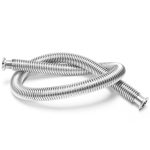
- Pressure According to the actual working pressure of the hose, check the nominal diameter and pressure gauge of the corrugation to decide whether to use the stainless steel mesh sleeve type.
- The nominal diameter of the size hose, the type of joint (mainly flange connection, screw connection, quick joint connection) and size, hose length.
- State According to the state of the hose, refer to the correct use and installation method of the metal hose and the optimal length of the hose during settlement compensation. The calculation of the length of the hose in various motion states, the minimum number of bending times and the minimum bending radius of the hose, etc. The parameters correctly select the length of the hose and install it correctly.
- Temperature The working temperature and range of the medium in the hose; the ambient temperature when the hose is working. When the temperature is high, the temperature correction coefficient of the working pressure of the metal bellows at high temperature must be used to determine the pressure after the temperature correction to determine the correct pressure level.
- The chemical properties of the medium conveyed in the media hose, according to the corrosion resistance parameter table of the hose material, determine the material of the hose parts.
6.Vacuum hose is mainly used in monocrystalline silicon production to achieve negative vacuum
Mainly used in steel belts
Steel strip corrugated pipe is also called steel strip reinforced polyethylene spiral corrugated pipe. It is a winding structure wall pipe with high density polyethylene (PE) as the matrix (inner and outer layer) and surface coated with adhesive resin steel strip. The tube wall structure consists of three layers: the inner layer is a continuous solid-wall PE inner layer tube, and the inner layer tube is wound with a ring-shaped corrugated steel strip reinforcement (formed with a steel plate into a “V” shape) outside the corrugated steel strip to enhance the exterior The outer layer of polyethylene is compounded to form a whole spiral corrugated pipe. Its typical structure is shown in the figure. The elastic modulus of steel is nearly 200 times that of polyethylene (the elastic modulus of carbon steel is about 190,000 MPa). Combining the advantages of metal and plastic is obviously an ideal way to achieve high rigidity and low consumption. High rigidity, high strength and the excellent characteristics of plastics such as corrosion resistance, abrasion resistance and flexibility are organically combined to give play to the advantages of both aspects, make up for the shortcomings of both aspects, and realize the unification of high performance and low cost.